Price Match
Now via Live Chat
Engine ventilation is a vital part of the air-cooled VW engine as it requires a constant flow of cool air into the engine bay. This cool air is drawn into the engine via a cooling fan located on the front of the generator inside the fan shroud on Type 1 Style engine and on the end of the crankshaft on Type 4 engines.
The cold air is fed through engine cooling louvres (vents) in the side of the Bus. Various patterns of engine cooling louvres were designed for the VW Type 2 over the years.

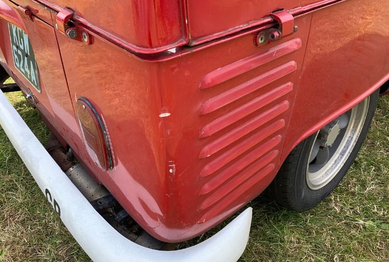
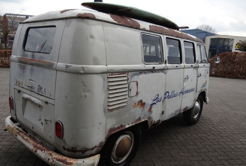
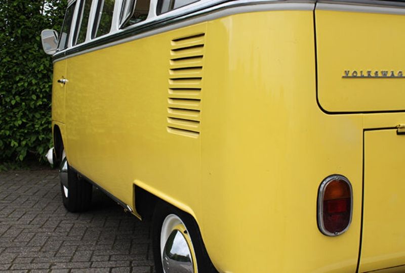
From the start of production in 1950 the engine ventilation was provided by eight louvres located on the rear quarter panel below the swage line of the Splitscreen Bus. These louvres were all outward facing and deluxe models were finished off with a chrome trim on the edge of each louvre. Panelvans of this generation had an extra 3 louvres just below the roof gutter to ventilate the load area.

In March 1955 and extra louvre was added below the swage line to help with engine cooling. These 9 louvres were still outward facing.

In March 1963 another louvre was added below the swage line. The 10 louvres were now inward facing and would remain in this design until the end of production of the Splitscreen Bus in July 1967.
The 8 engine cooling louvres on the Single Cab and Double Cab Pick-up was introduced at the start of production and didn’t change until August 1965 when a 9th louvre was added.
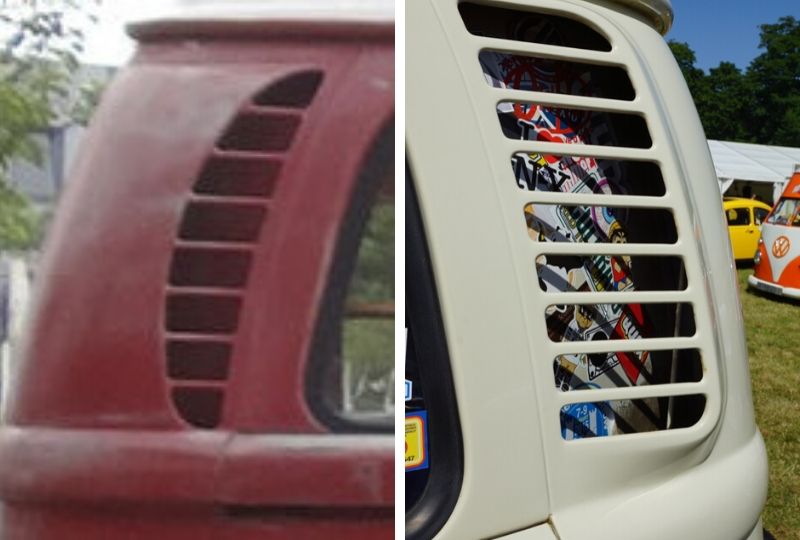
With the introduction of the Baywindow Bus in August 1967 a new design in engine cooling louvres was incorporated into the design of the Bus. They were moved from below the rear swage line in the rear quarter panel to the top of the rear corners of the rear of the Bus.

The Early Bay incorporated a more rounded design which was more than adequate for the 1600cc engine that powered the Bus. In 1971 the Type 4 engine was introduced and with it a new design in ventilation.
The Late Bay’s engine cooling louvres were more square in shape and much larger in size to help cool the larger engine.